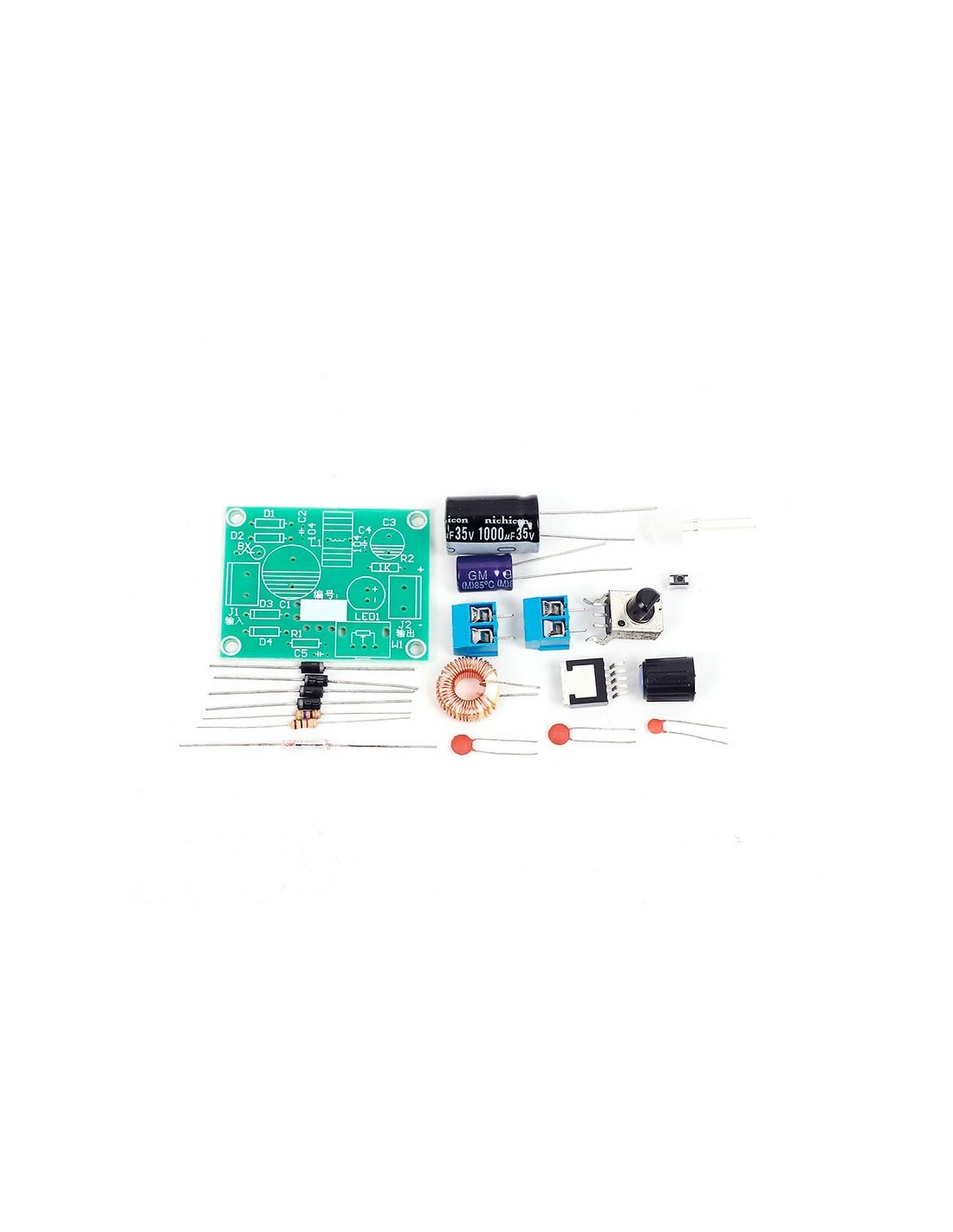
DIY Kit LM2596 Adjustable Voltage Stabilizer

DIY Kit LM2596 Adjustable Voltage Stabilizer

Регулируемый стабилизатор напряжения LM2596 (DIY KIT)

00858
Нет в наличии
3,80 €


1. Function:

It can input non-stable alternating current and output adjustable voltage. Its minimum output voltage is 1.23V and the maximum output current is 3A. LM2596 contains fixed frequency oscillator (150KHz) and benchmark voltage stabilizer (1.23 V), and has perfect protection circuit, current limit, heat cut-off circuit and so on. This circuit has the advantages of high efficiency and low heat. It can make full use of the various idle transformers around you to make the stable voltage stable power supply. 

2. Working voltage:

LM2596 is the switch of voltage stabilizer and step down circuit. Please ensure that the input voltage is higher than the output voltage. The general input is 3.2V - 40V, and output is 1.23V-35V.

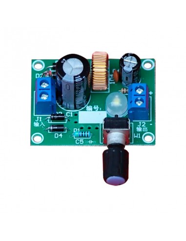
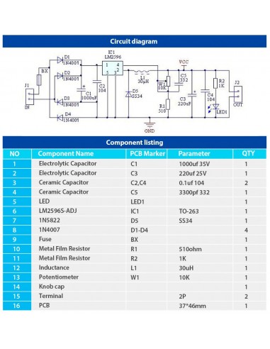
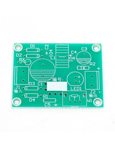
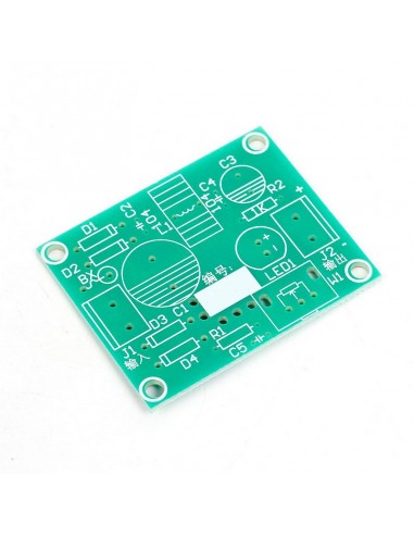
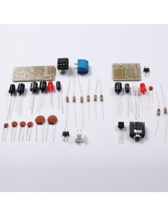
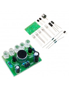
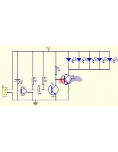
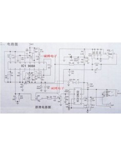
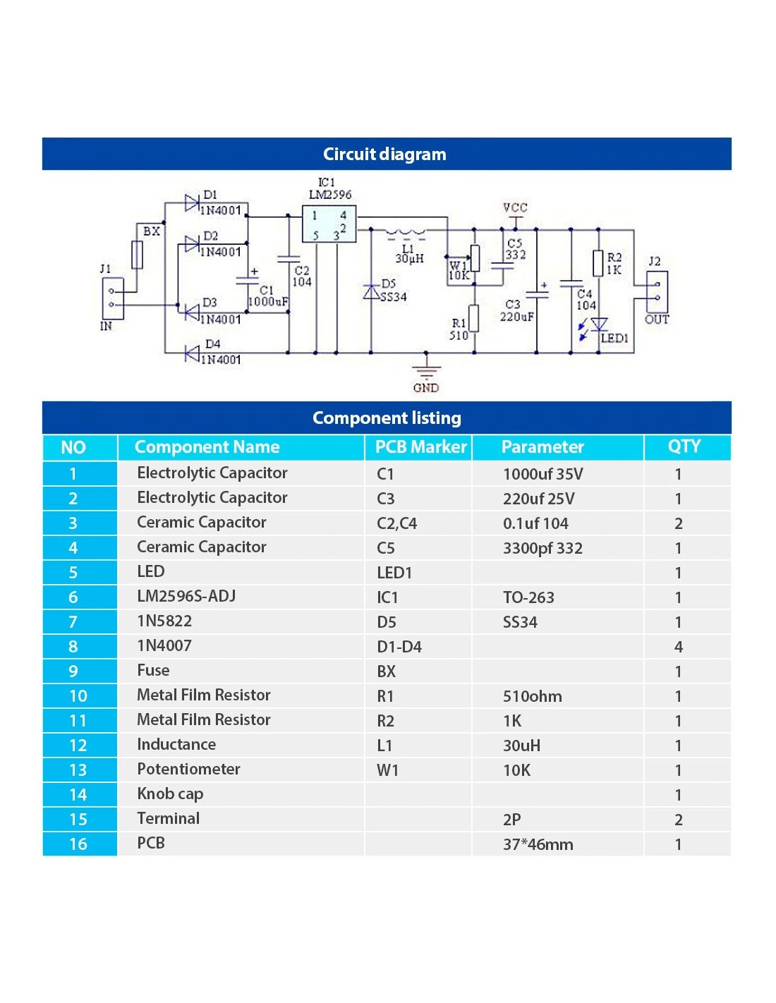
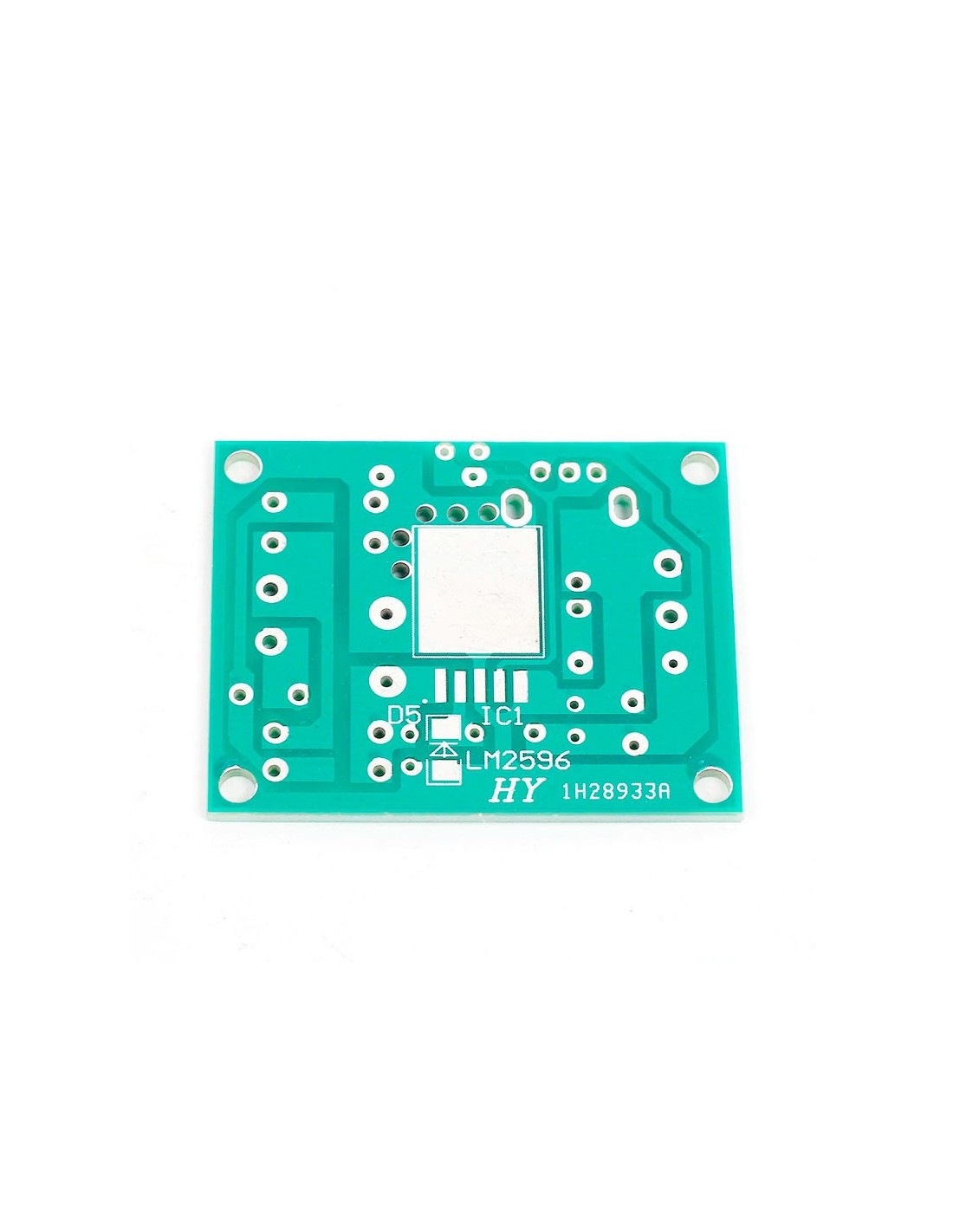
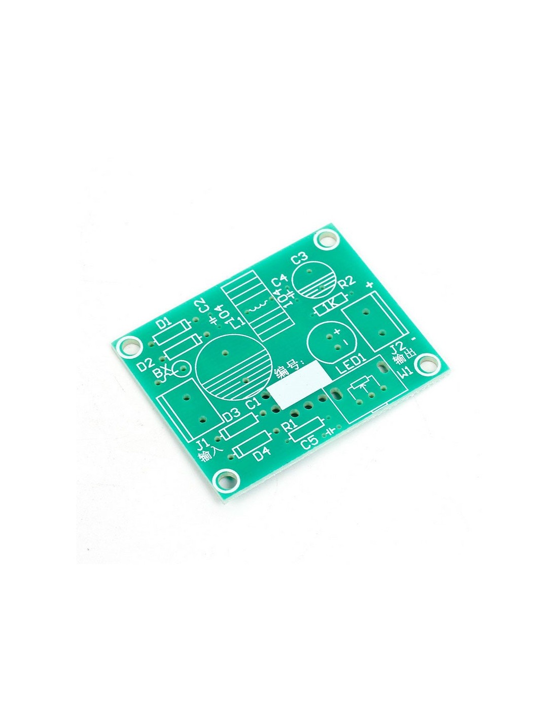
3. Circuit principle:

The non-stationary AC voltage input of J1 was rectified by d1-d4, C1 and C2 filtered as the input voltage of LM2596 output the stable DC voltage from J2 through the LM2596. C3, C4 is the output filter capacitance. R2 and LED2 constitute the indicator circuit. LED1 is 8mm white LED. Its brightness can roughly indicate the output voltage. If the brightness is too bright, you can increase the resistance of R2 properly. L1 is a special inductance, which acts as an energy conversion. D5 is the Schottky diode, which plays a continuous role in the circuit. C5 interferes the circuit. The output voltage of R1 and W1 can be calculated by the following formula: Vo=1.23(1+W1/R1)

No reviews

16 других товаров в той же категории:

Товар добавлен в список желаний
Товар добавлен для сравнения.

На нашем интернет-сайте используются файлы куки. Файлы куки помогают обеспечивать надлежащее функционирование интернет-страницы и ее совершенствование, поэтому необходимые файлы куки (технические, функциональные и аналитические) устанавливаются автоматически. Чтобы индивидуализировать ваш опыт поиска в интернете и предоставлять предложения, которые будут актуальны именно для Вас, на интернет-странице также используются целевые файлы куки. Нажатием клавиши «соглашаюсь» Вы соглашаетесь с установкой и использованием целевых файлов куки. Вы сможете отозвать свое согласие в любое время, изменив установки своего интернет-браузера или стерев записанные файлы куки. Более подробная информация предоставляется - в политике файлов куки