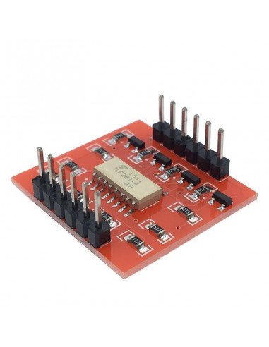
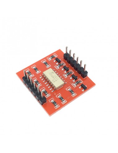
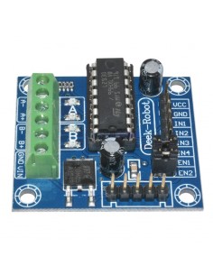
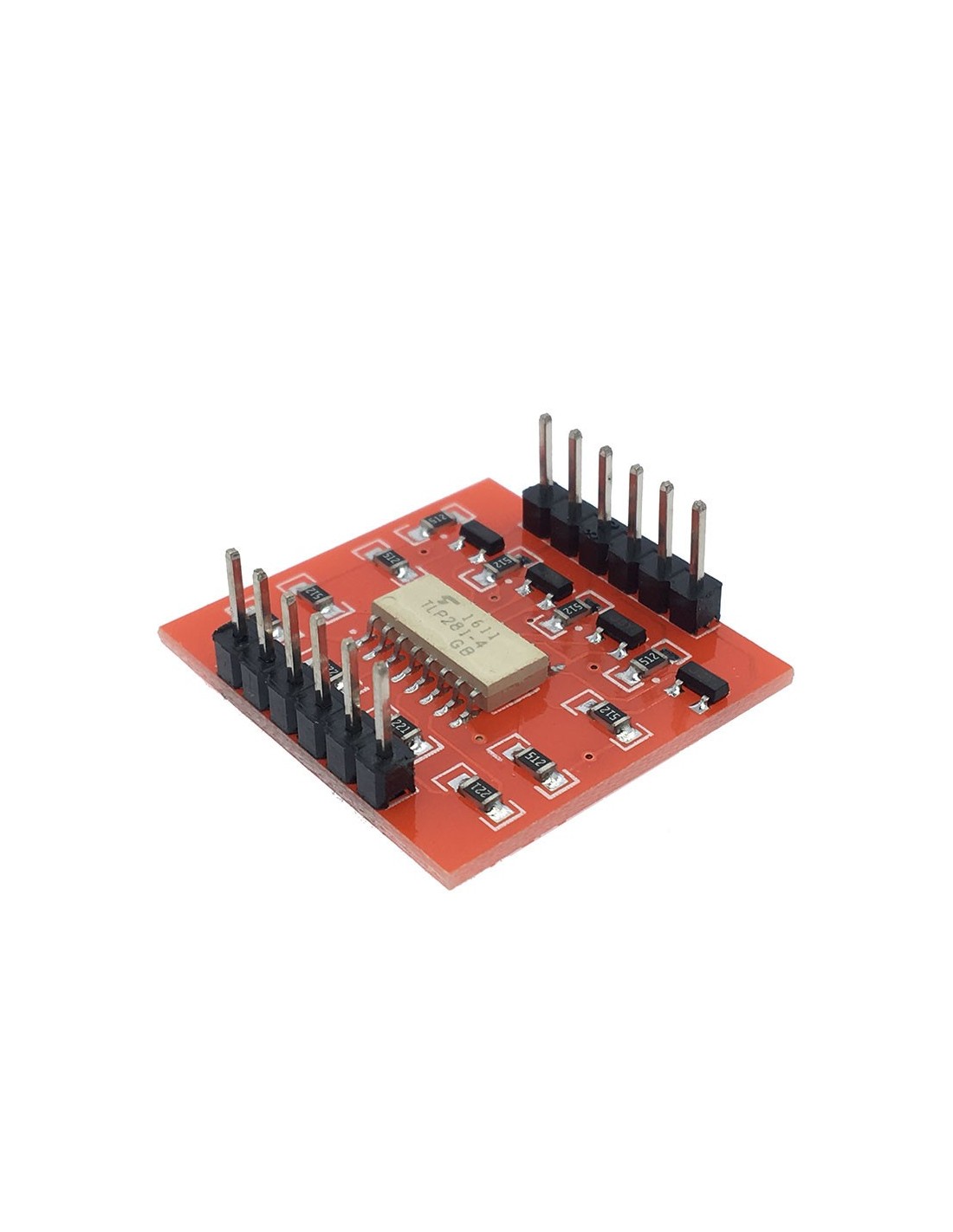
This board is helpful for connecting digital systems (like a 5V microcontroller) to a high-voltage or noisy system. This board electrically isolates a controller from the high-power system by use of an opto-isolator IC.
- This IC has four LEDs and four photodiodes built-in.
- This allows the low-voltage side to control a high voltage side
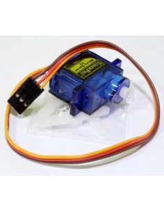
- We often use this board to allow a microcontroller control servos
- or other motors that use a higher voltage than the TTL logic on the (3.3V or 5V) micro,
- and may cause electromagnetic interferance with our system as the motors turn on and off.
- This board will isolate the systems, creating a type of electrical noise barrier between devices
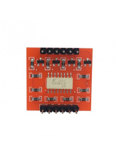
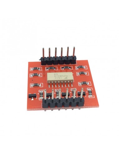
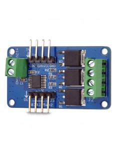
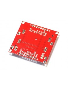
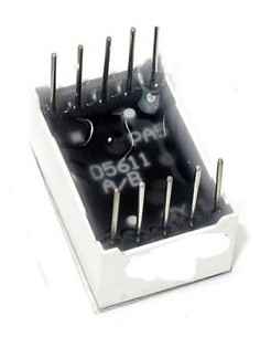
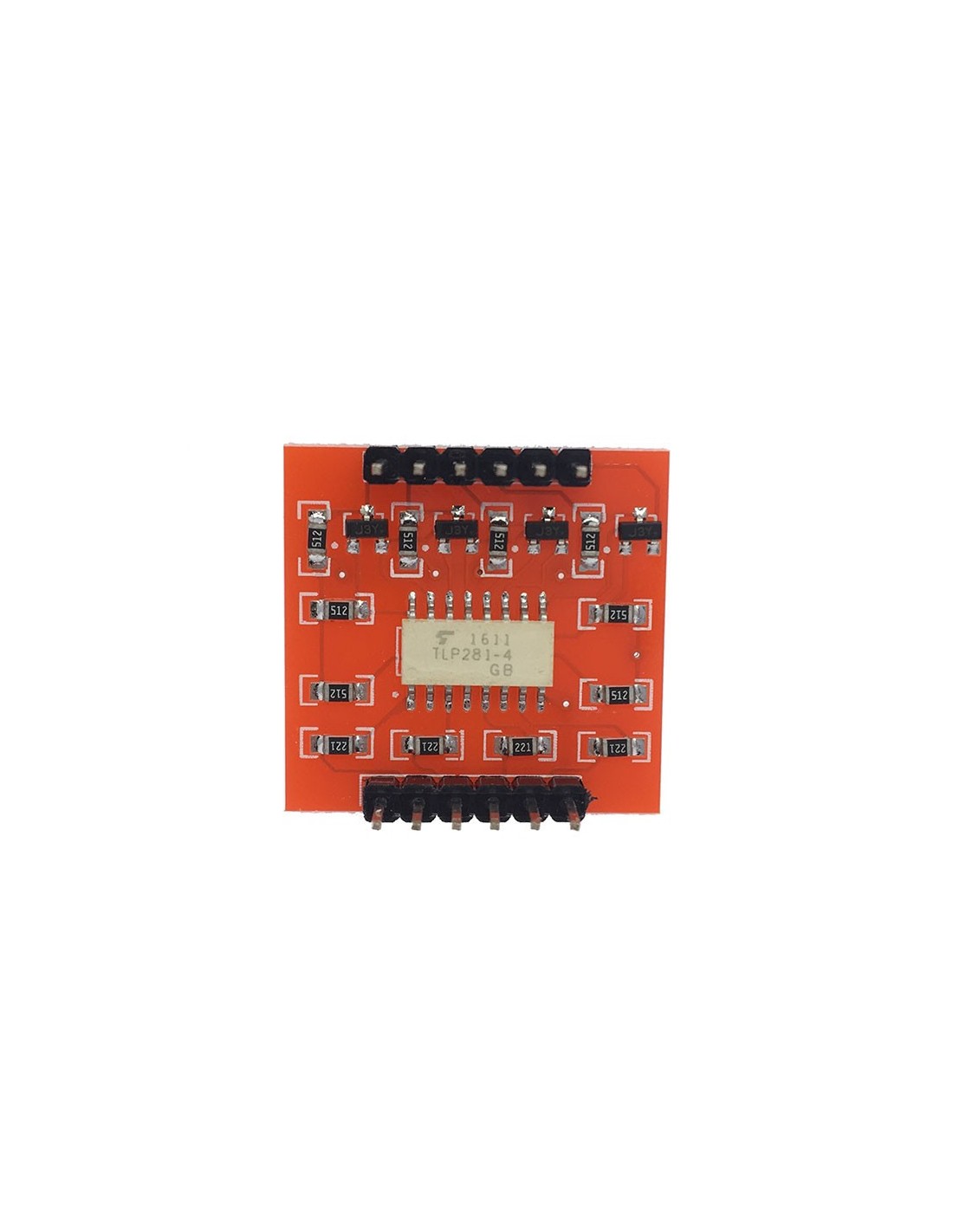
- This breakout board uses the TLP281 optoisolator and discrete transistors to correct the logic.
- Comes with four channels.
- Great for use in noisy circuits where signal lines require electrical isolation
- A normal LED opto-isolator will invert the logic of a signal.
- We threw some transistors on this compact board to correct the inversion.
- What you put into the IN pins, will be replicated on the the OUT pins, but at the higher voltage (HV)
Features:
- Use of low level control high level.
- Such as the use of single chip microcomputer 3V or 5V voltage 9V or 12V voltage control
- HVCC maximum not more than 24V.
- Outlet OUT1 / OUT2 / OUT3 / OUT4 output current is equal to the largest HVCC / 5.1K, maximum absorption current 500mA
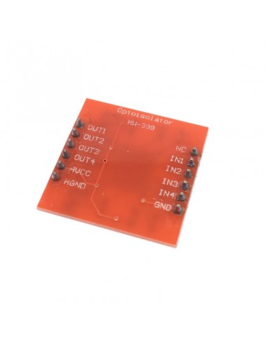
- Input: IN1 / IN2 / IN3 / IN4, SCM or for Ard uino IO port,
- GND with single-chip microcomputer or for Ard uino board GND connection.
- IN1 / IN2 / IN3 / IN4 respectively control the OUT1 / OUT2 / OUT3 / OUT4
- Output: OUT1 / OUT2 / OUT3 / OUT4
- Output: HVCC: Connection is control of high voltage anode,
- HGND connection is control of high voltage anode
- PCB Size: 25*24mm/0.98*0.94
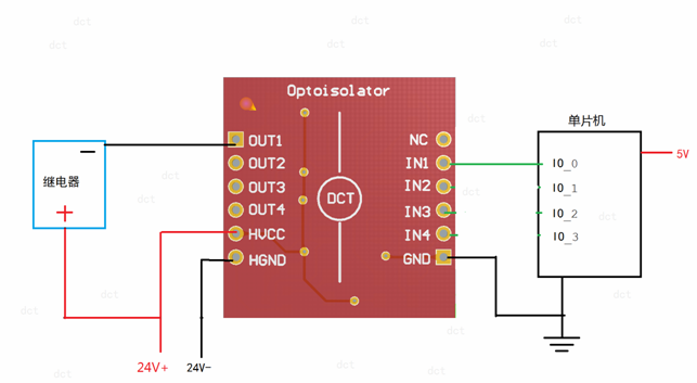
Use examples
The following example shows how to use the microcontroller's IO port to control the 24V motor rotation. The motor operating voltage in the figure is 24V, the red "+" indicates the positive power of the motor, and the black "-" indicates the negative power supply of the motor. When the microcontroller IO_0 output high, the motor rotation, when the IO_0 port output low when the motor stops rotating.


