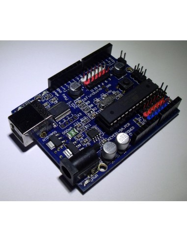
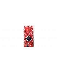
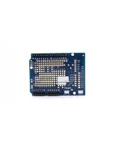
Clone Arduino Duemilanove board with additional connectors for sensors.
Overview
Arduino Duemilanove («2009») is built on the microcontroller ATmega328. It has 14 digital input / outputs (of which 6 can be used as PWM outputs), 6 analog inputs, a 16 MHz crystal oscillator, connector USB, power jack, ICSP and reset button. To work platform must connect to a computer via a USB cable or supply power using the adapter AC / DC, or battery.
Power
Arduino Duemilanove can be powered via the USB connection or an external power supply. Power source is selected automatically.
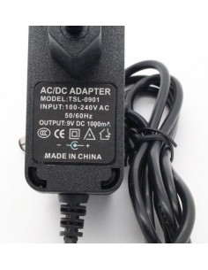
External power supply (not USB) can be supplied through a voltage converter AC / DC (power supply unit) or battery. Voltage converter is connected by connector 2.1 mm with a central positive pole. The wires from the battery terminals are connected to Gnd and Vin power connector.
The platform can work with external power supply 6 V to 20 V. For supply voltages below 7, 5V output can deliver less than 5 V, while the platform can be unstable. When using the voltage above 12 V voltage regulator may overheat and damage the board. Recommended range of 7 V to 12 V.
Power terminals:
- VIN . Input is used to supply power from an external source (in the absence of 5 V from the USB connector or other variable power supply). Supply voltage occurs through this conclusion.
- 5V . Voltage source used to power the microcontroller and components on the board. Power may be supplied from the output through the VIN voltage regulator or connector USB, or other regulated voltage source 5 V.
- 3V3 . Voltage at 3.3V FTDI chip generated on the platform. Maximum current consumption of 50 mA.
- GND . Ground terminals.
Memory
The ATmega168 has 16 KB of flash memory for storage of program code and microcontroller ATmega328, in turn, has a 32KB (both 2 KB is used to store the boot loader.) ATmega168 has 1 KB of SRAM and 512 bytes of EEPROM (which can be read and written with the EEPROM library ), and ATmega328 - 2 KB of SRAM and 1 KB EEPROM.
Inputs and Outputs
Each of the 14 digital pins on the Duemilanove, using the function pinMode () , digitalWrite () , and digitalRead () , can be configured as input or output. They operate at a voltage of 5 V. Each pin has a pull-up resistor (disconnected by default) of 20-50 kOhms and can source up to 40 mA. Some pins have specialized functions:
- Serial Bus: 0 (RX) and 1 (TX) . Used to receive (RX) and transmit (TX) data TTL. These pins are connected to the corresponding pins of the chip serial bus FTDI USB-to-TTL.
- External Interrupt 2 and 3 . These pins can be configured to trigger an interrupt on a low value, a rising or falling edge, or when the value changes. Detailed information can be found in the function description attachInterrupt ().
- PWM: 3, 5, 6, 9, 10, and 11. Any of the terminals provides PWM resolution of 8 bits by using the analogWrite ().
- SPI: 10 (SS), 11 (MOSI), 12 (MISO), 13 (SCK). These pins Feedback SPI, which, although provided by the underlying hardware, is not included in the language of Arduino.
- LED: 13. Built-in LED connected to digital pin 13. If the value on the output is held high, the LED lights.
Platform Duemilanove has 6 analog inputs, each 10 bits of resolution (ie 1024 different values). Standard conclusions are measuring range up to 5 with respect to ground, however it is possible to modify the upper limit by the AREF pin and function analogReference (). Some conclusions have additional features:
- I2C: 4 (SDA) and 5 (SCL). Through conclusions communicates I2C (TWI), which is used to create a library Wire.
An extra pair of pins platform:
- AREF. Reference voltage for analog inputs. Used with analogReference ().
- Reset. Low signal at pin resets the microcontroller. Typically used to connect the reset button on the expansion card, closing access to the button on the board Arduino.
Link
Platform Arduino Duemilanove several units to communicate with a computer, another Arduino, or other microcontrollers. ATmega168 and ATmega328 support serial UART TTL (5V), digital pins 0 (RX) and 1 (TX). Installed on board FTDI FT232RL chip directs the interface via USB, drivers and FTDI (included in the Arduino) provide virtual COM port on a computer program. Monitoring serial bus (Serial Monitor) program Arduino allows you to send and receive text data when connected to the platform. The RX and TX LEDs on the platform will blink when transmitting data via FTDI chip or USB connection (but not when using serial communication via pins 0 and 1).
SoftwareSerial library allows for serial communication on any of the digital outputs Duemilanove.
ATmega168 and ATmega328 support interfaces I2C (TWI) and SPI. The Arduino software includes a Wire library to usability bus I2C. More information is available in the documentation. To use the SPI, refer to the technical data of the ATmega168 and ATmega328.
Programming
Programmed via software platform Arduino. From the menu Tools> Board selected «Arduino Diecimila or Duemilanove w / ATmega168» or «Arduino Duemilanove w / ATmega328» (according to the established microcontroller). Detailed information is in the directory and instructions .
The ATmega168 and ATmega328 are supplied with a recorded loader, facilitating entry of new programs without the use of an external hardware programmer. Communication takes the original protocol STK500.
You can also bypass the bootloader and program the microcontroller through the conclusions ICSP (in-circuit programming). Detailed information can be found in this manual.
Automatic (Software) Reset
Duemilanove designed so that the new code before recording restart performed by the program, rather than by pressing buttons on the platform. One of the lines FT232RL, data flow control (DTR), connected to the microcontroller ATmega328 conclusion reboot via a 100 nF. Activation of this line is supply low-level signal, resets the microcontroller. Program Arduino, using this function to upload code by pressing the Upload in the Arduino environment. Submission of low-level signal to DTR coordinated with the start of writing code that reduces the loader timeout.
Function has another application. Reload Duemilanove happens every time you connect to the Arduino program on a computer running Mac X or Linux (via USB). The following half-second after reboot bootloader works. During programming intercept the first few bytes of code to avoid making incorrect data platform (all except the code of the new program). If you are debugging single sketch recorded in the platform configuration or other data when it first starts, make sure that the program on the computer waits a second before transmitting data.
On the Duemilanove has an option to disable automatic restart line corresponding to the line break. Contacts chips with both ends of the link may be connected for the purpose of recovery. The line labeled «RESET-EN». Disable automatic restart is also possible by connecting a resistor between 110 ohm source 5 V and this line. Detailed information can be found in the appropriate forum thread.
Current protection USB connector
In Arduino Duemilanove integrated self-healing fuse (automatic), which protects the computer USB port short circuit and overcurrent. Although virtually all computers have this protection, however, this fuse provides an additional barrier. Fuse srabatyvat when the current 500 mA USB port and opens the circuit as long as normal currents will not be impeccably renovated.
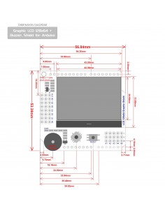
Physical characteristics
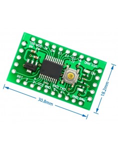
Length and width of the Duemilanove PCB constitute 6.9 and 5.3 cm, respectively. USB connector and power connector extend beyond the data size. Three holes in the board allow secure it to the surface. Distance between digital terminals 7 and 8 equals 0.4 cm, although among other findings, it is 0.25 cm


")
")
")


