Overview
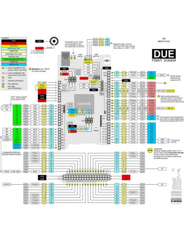
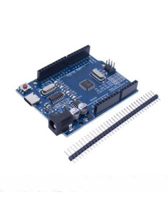
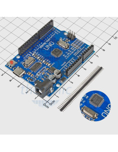
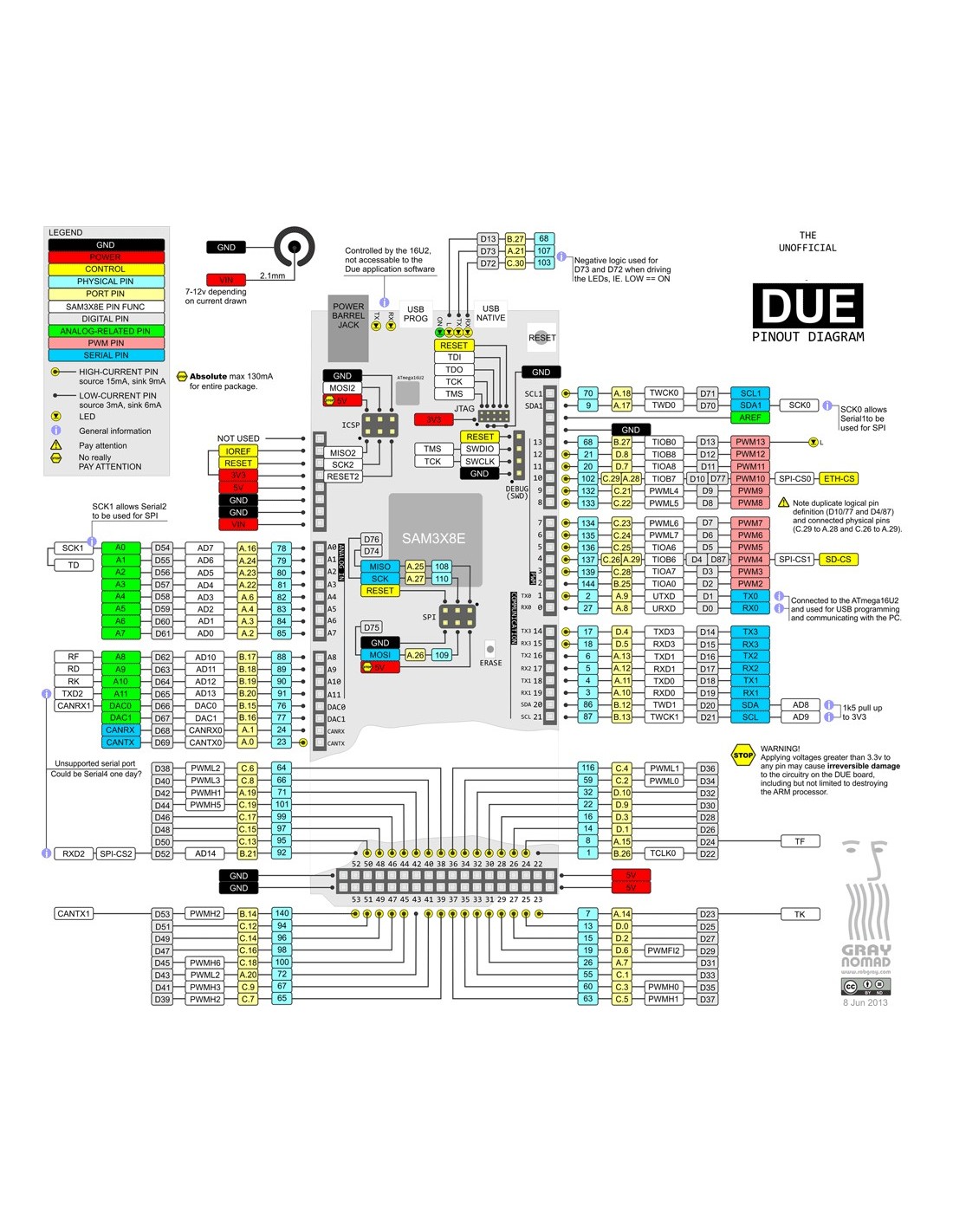
Due arduino - microcontroller board based on the processor ARM Cortex Atmel SAM3X8E-M3 ( description ). This is the first Arduino board on a 32-bit microcontroller with ARM core. It has 54 digital input / output (of which 12 can be operated under the PWM outputs), 12 analog inputs, 4 UARTa (hardware serial ports), a clock generator 84 MHz, USB connection to support OTG, 2 DAC (digital-to- analog converter), 2 TWI, power connector, SPI, connector JTAG, reset button and a button to erase.
Attention! Unlike other boards Arduino, Arduino Due operates from 3.3 V maximum voltage that can withstand input / output is 3.3 V. At higher voltages, for example, 5 V, the conclusions of the Arduino Due, you can damage the board.
The board contains everything needed to support the microcontroller. To start using it, simply connect it to the computer using the micro-USB, or be powered with AC / DC converter or battery. Due compatible with all expansion cards Arduino, operating from 3.3V and pinout with Arduino 1.0.
Due repeats pinout pinout Arduino 1.0:
- TWI: Conclusions SDA and SCL are located near the terminal AREF.
- Conclusion IOREF, which allows using the correct configuration to adapt the expansion card connected to the voltage outputted Arduino. Due to this expansion card and can be compatible with 3.3-volt type Due boards and motherboards based on AVR, operating from 5 V
- Unconnected conclusions are reserved for future use.
Benefits of ARM
Due installed on 32-bit ARM core, superior to conventional performance 8-bit microcontrollers. The most significant differences are:
32-bit kernel, allows you to perform operations on the data width of 4 bytes for 1 cycle (for more information see page int type ).
- frequency processor (CPU) 84 MHz.
- 96 KB of RAM.
- 512 KB flash memory for program storage.
- Controller DMA, which relieves the CPU from performing intensive memory operations.
Features
| Microcontroller |
AT91SAM3X8E |
| Operating voltage |
3.3 |
| Input Voltage (recommended) |
7-12 In |
| Input Voltage (Max) |
6-20 In |
| Digital Inputs / Outputs |
54 (12 of which is realized output PWM ) |
| Analog inputs |
12 |
| Analog outputs |
2 (DAC) |
Common DC output
on all inputs / outputs |
50 mA |
| Current DC output 3.3 |
800 mA |
| Constant current through the 5 V output |
800 mA |
| Flash memory |
512 KB available for all custom applications |
| RAM |
96 KB (two banks of 64 KB and 32 KB) |
| Clock speed |
84 MHz |
Food
Food Arduino Due can be done through USB connector or an external power supply. Power supply selection is done automatically.
External (non-USB) power supply can be either AC / DC converter («wall wart» - adapter in one housing with a fork) or battery. The adapter connects to the power supply board 2.1mm plug with a central positive contact. Battery terminals are connected to the contacts Gnd and Vin connector POWER. The board can operate with an external supply of 6 to 20 V. However, if the supply voltage drops below 7 at 5 V output may be less than five volts and the board will be unstable. If the voltage is more than 12 V, the voltage regulator may overheat, causing damage to the board. Recommended voltage range - from 7 to 12 V.
Below are the findings of supply:
- VIN . This is the input voltage to the board Arduino, when it is powered by an external power source (as opposed to 5 volts supplied through the USB connection or other regulated power source). Supply voltage can be supplied to this conclusion, or removed from this conclusion in the case of plug-in power supply.
- 5V . This conclusion is a regulated output voltage of 5 V with built-in stabilizer on the board. The board itself can be powered via the DC power connector (7-12 V) or via a USB connector (5 V) or via terminal VIN on the board (7-12V). Supply voltage across pins 5 V and 3.3 V is applied to bypass the regulator and can damage your board. We do not recommend doing so.
- 3.3V . 3.3V generated integrated stabilizer. Maximum output current of 800 mA. The stabilizer also provides power microcontroller SAM3X.
- GND. Earthmoving conclusions.
- IOREF . This conclusion provides the Arduino reference voltage at which the microcontroller works. Correctly configured expansion board can consider the voltage at IOREF and select the appropriate power supply, or allow the use of output voltage converters to work with 5 V or 3.3 V.
Memory
Flash memory is 512KB SAM3X (2 units of 256 KB) for storing programs. Downloader (butloder) recorded Atmel during production and stored in specially designated for him ROM. The available RAM is 96 KB in two adjacent banks - 64 KB and 32 KB. All available memory (flash memory, RAM and ROM) can be addressed directly as a flat address space.
It is possible to erase the flash memory using the built SAM3X erase button. When this current is removed from the microprocessor loaded program. To erase a few seconds and then hold the erase button when the power board.
Inputs and Outputs
- Digital inputs / outputs: 0 to conclusions 53
Each of the 54 digital pins Due can be used as input or output functions using pinMode () , digitalWrite () and digitalRead () . They operate from 3.3 V. Each output can deliver (as a source) current 3 mA or 15 mA, depending on the output, or receive (as a receiver) or current 6 mA 9 mA in Whereupon from output. They also have internal pull-up resistors (disabled by default) nominal value of 100 ohms. In addition, some conclusions are assigned specific functions:
- Serial line: 0 (RX) and 1 (TX)
- Serial Line 1: 19 (RX) and 18 (TX)
- Serial Line 2: 17 (RX) and 16 (TX)
- Serial Line 3: 15 (RX) and 14 (TX)
These results are used for reception (RX) and transmit (TX) data serial TTL (level 3.3). Pins 0 and 1 are connected to the corresponding pins serial controller ATmega16U2 USB-to-TTL.
- PWM : findings from 2 to 13
are implemented on an 8-bit PWM output with the function analogWrite () . PWM resolution can be changed by using the analogWriteResolution () .
- SPI : connector SPI (ICSP connector on other boards Arduino)
These pins are used for communication using the SPI library SPI . SPI signals are displayed on the central 6-pin connector, which is physically compatible with the Uno, Leonardo and Mega2560. SPI connector can only be used for communication with other devices SPI, but not for programming SAM3X technology in-circuit serial programming (ICSP). Due to the SPI also has advanced features available when using an advanced method for SPI Due .
- CAN : CANRX and CANTX
These findings supported communication protocol CAN, but so far do not support programming interfaces (API) Arduino.
- " L " LED : 13
built-in LED connected to digital pin 13. At a high level signal on this output, the LED turns on when low - off. Perhaps also subtract brightness LEDs as pin 13 is output PWM.
- TWI 1: 20 (SDA) and 21 (SCL)
- TWI 2: SDA 1 and SCL 1
On these findings using the library Wire liaison for TWI.
- Analog inputs: findings from A 0 to A 11
Arduino Due board has 12 analog inputs, each of which can provide 12-bit resolution (ie 4096 different values). The default is 10-bit resolution for compatibility with other boards Arduino. ADC resolution can be changed using the analogReadResolution () . Due analog moves make measurements from ground level to a maximum of 3.3 V. Annex to these conclusions voltage above 3.3V will damage the crystal SAM3X. Function analogReference () Due to be ignored.
AREF pin is connected to the analog output voltage reference SAM3X through resistor bridge. To activate the AREF pin must unsolder with PCB resistor BR1.
- DAC 1 and DAC 2
on leads DAC DAC 1 and DAC 2 provides reliable analog outputs with 12-bit resolution (4096 levels) by using the analogWrite () . These findings can be used to create audio, using the library Audio .
Other findings:
- AREF
reference voltage for the analog inputs. Used with analogReference ().
- Reset
- Low level on this line resets the microcontroller. Typical application output Reset - adding the reset button on the expansion card, which overlaps the button on the microcontroller.
Link
In Arduino Due have some tools to interact with the computer, the Arduino and other microcontrollers, as well as a variety of devices, such as phones, tablets, cameras, etc. SAM3X has one hardware UART and three USARTa hardware for serial communication TTL-level ( 3.3).
The programming port is connected to ATmega16U2 , providing virtual COM port for software on a connected computer. (To determine this device Windows PC required file. Inf, also on machines with OSX and Linux fee will automatically be recognized as a COM port). 16U2 chip is also connected with the hardware UARTom SAM3X. Serial Bus and on the findings RX0 TX0 provides conversion Serial-to-USB for programming the microcontroller through ATmega16U2. In the Arduino software includes a serial bus monitor that gives the board the ability to send and receive simple text messages. The RX and TX LEDs on the board will flash when data is being transferred through the crystal and ATmega16U2 via USB connection to your computer (but not during serial communication on pins 0 and 1).
Own USB port (Native USB port) is connected to SAM3X. This allows for serial communication (CDC) through USB. This provides a connection to the monitor serial bus, or other applications on your computer. It also gives the opportunity to emulate Due to the attached computer USB mouse or keyboard. To use these features, see the manual pages library mouse and keyboard .
Own USB port can also operate as a USB host for connecting peripheral devices such as mice, keyboards and smartfotonov. To use these features, refer to the manual pages USB host .
SAM3X controller supports further communication interfaces TWI and SPI. Arduino software includes a Wire library to facilitate bus operation TWI; see a more detailed description in the documentation . For communication via the SPI library use SPI .
Programming
Arduino Due can be programmed by software Arduino ( download ). More detailed information is contained in the directory .
 Loading programs SAM3X differs from that of microcontrollers AVR, being on other boards Arduino, since it is necessary to erase the flash memory before reprogramming it. Loading a crystal controlled from the ROM controller SAM3X and runs only when the flash memory chip is empty.
Board can be programmed via both USB ports, although it is recommended to use the programming port, due to the fact that it supports erasing the crystal:
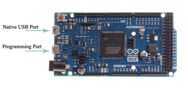
- Programming port : To use this port, select the Arduino IDE as your board "Arduino Due (Programming Port)". Connect the programming port fees Due (closest to the DC power input connector) to your computer. The programming port uses a chip 16U2 as a converter USB-to-serial, coupled to the first controller UARTom SAM3X (RX0 and TX0). Two pins are connected to terminals 16U2 Reset and Erase SAM3X. Opening and closing the programming port connected to the transmission rate of 1200 bits per second, invokes the "hardware erase" chip SAM3X, activation conclusions Erase and Reset on SAM3X before establishing a connection with the UART. This is the recommended port for programming Due. Hardware erasing more reliable than "erasing software" that occurs on its own USB port, and will work even if the damage of the main microprocessor.
- Net port : To use this port, select the type of your Arduino IDE board "Arduino Due (Native USB Port)". Own USB port connected directly to SAM3X. Connect the USB port of your own Arduino Due (closest to the button Reset) to your computer. Opening and closing of its own port at a baud rate of 1200 bit per second invokes the "erasure software": flash memory is erased and the board is restarted by the loader. If the main microcontroller damaged for any reason, it is likely that the software will not work erasing, as this procedure on SAM3X occurs entirely in software. Opening and closing of its own port on the other transmission speeds will not cause a reset SAM3X.
Unlike other boards Arduino, used to load avrdude, Due relies on bossac.
Source code is available for ATmega16U2 archive Arduino . By ISP connector can be connected to an external programmer (overwriting boot DFU). More information can be found in the instructions to assist users .
Current protection USB connector
On Arduino Due has resettable fuse, whose purpose - to protect the USB ports on your computer from a short-circuit and overcurrent. Despite the fact that most computers have built-in thermal protection, the fuse provides additional protection. When the current through the USB port more than 500 mA fuse connection automatically terminates prior to the termination of an overload or short circuit.
Physical characteristics and compatibility with expansion cards
The maximum length of PCB Arduino Due is 4 inches, width - 2.1 inches, excluding USB connectors and power connectors, which act for the listed dimensions. Three screw holes allow to fix the charge on the surface or in the body. Note that the distance between the digital terminals 7 and 8 is 160 mils (0.16 ", 4.064 mm) and not multiple gaps 100 mils (2.54 mm) between the other terminals.
Arduino Due is made compatible with most expansion cards developed for Uno, Diecimila or Duemilanove. Digital pins 0 to 13 (and the adjacent AREF pin and GND), analog inputs 0 to 5, power connector, "ICSP" (SPI) are arranged equally on all boards. Moreover, the main UART (serial port) is located on the same conclusions (0 and 1). Please note that the bus I 2 C is located in the Arduino Due to other findings (20 and 21), not because the Duemilanove / Diecimila (analog inputs 4 and 5).
")
")
")


